
What's new in SunSolve Power
A comprehensive overview of the significant enhancements and new features recently introduced in SunSolve Power, from performance improvements to advanced modeling capabilities.

· Malcolm Abbott · 5 min read
SunSolve Power has undergone significant evolution between Version 6 and Version 7, with numerous enhancements that strengthen its position as the leading physics-based simulation software for solar cell and module design optimization. As our software continues to evolve rapidly, this post serves as a comprehensive snapshot of all the major changes and new features that have been introduced as of today’s release.
From substantial performance improvements to cutting-edge modeling capabilities for next-generation solar technologies, Version 7 represents a major step forward in our mission to provide engineers with the most accurate and efficient simulation tools available.
What’s new in SunSolve Power?
- 50% more computing power for faster solutions
- An improved user interface
- Equivalent-circuit solving of tandem solar cells
- Thin films with spatially non-uniform thickness
- Automatic optimisation routines
- IBC metallisation pattern (estimated release September 2025)
- Improved control over the series resistance calculation
- Cell-level variation in equivalent circuit inputs
- Future upgrades
50% more computing power for faster solutions
SunSolve 7 delivers 50% more computing power combined with an improved solving engine, leading to significantly faster solutions for engineers. This performance boost means less time waiting for results and more time focusing on design optimization.
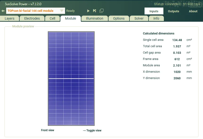
An improved user interface
The user interface has been upgraded for clearer definition of simulation inputs, making it easier for engineers to set up and configure their models.
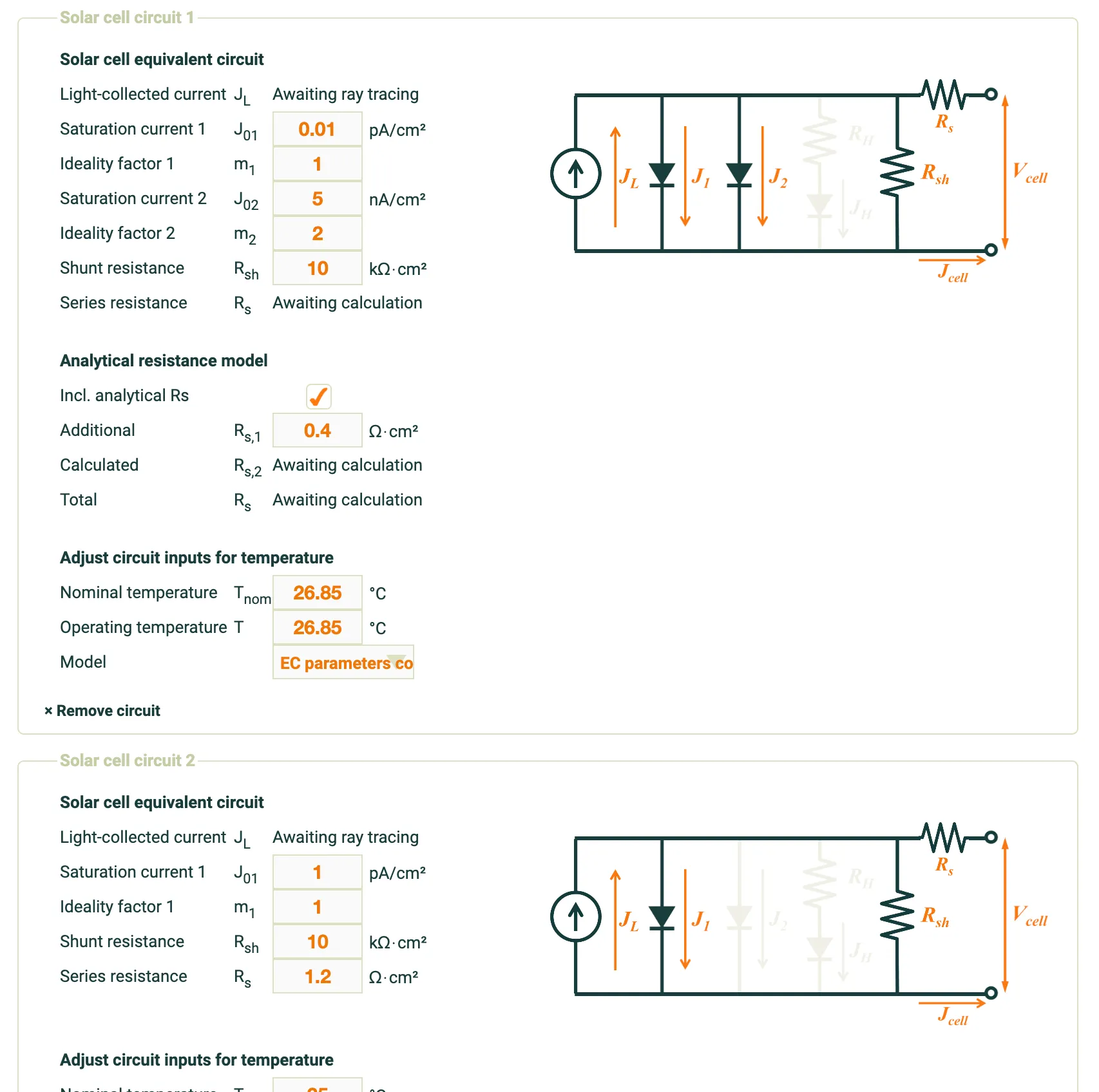
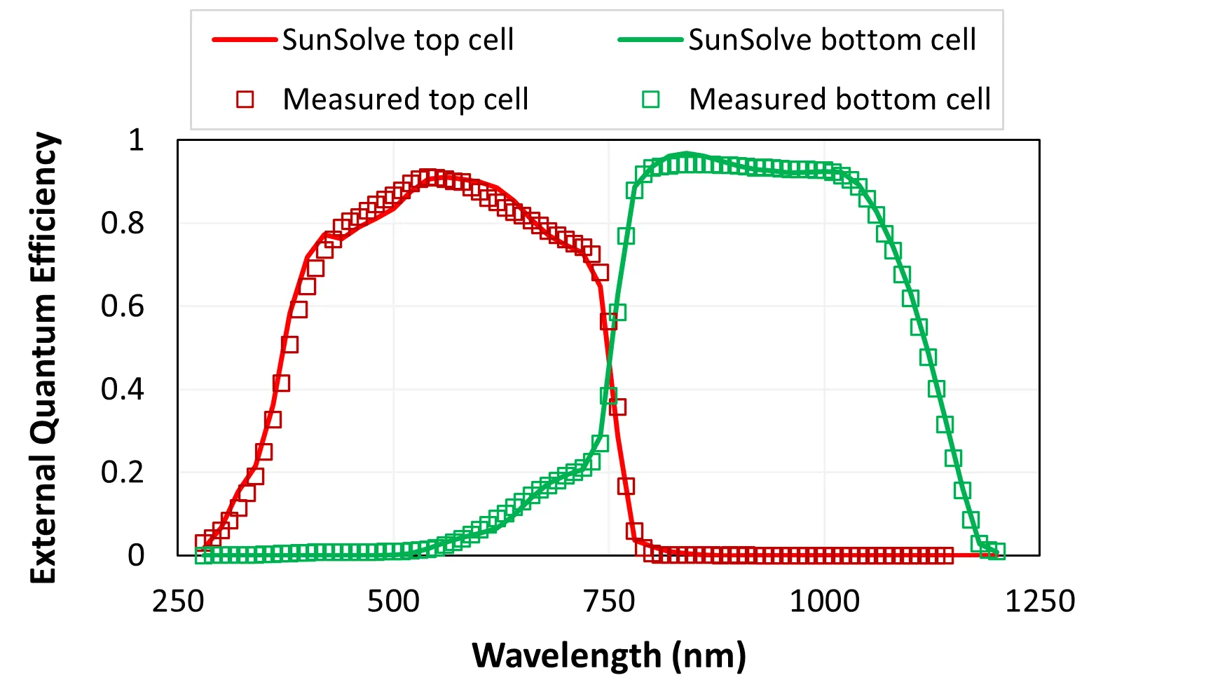
Equivalent-circuit solving of tandem solar cells
While solving the optics of multiple layers has been supported in SunSolve for some time, SunSolve 7 adds the ability to assign layers to different circuits to represent multi-terminal devices. This feature not only improves the capabilities for modeling tandems in SunSolve Power, but also enables modeling of tandem cells within larger systems in SunSolve Yield.
Thin films with spatially non-uniform thickness
By default, films in SunSolve have a uniform thickness. SunSolve 7 introduces the ability to represent films with varying thickness defined by top-hat or Gaussian distribution functions. Non-uniformity in film thickness usually results from the deposition technique and can be particularly severe in films deposited onto textured surfaces. 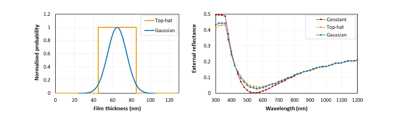
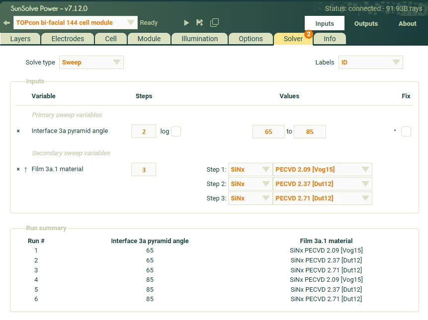
Automatic optimisation routines
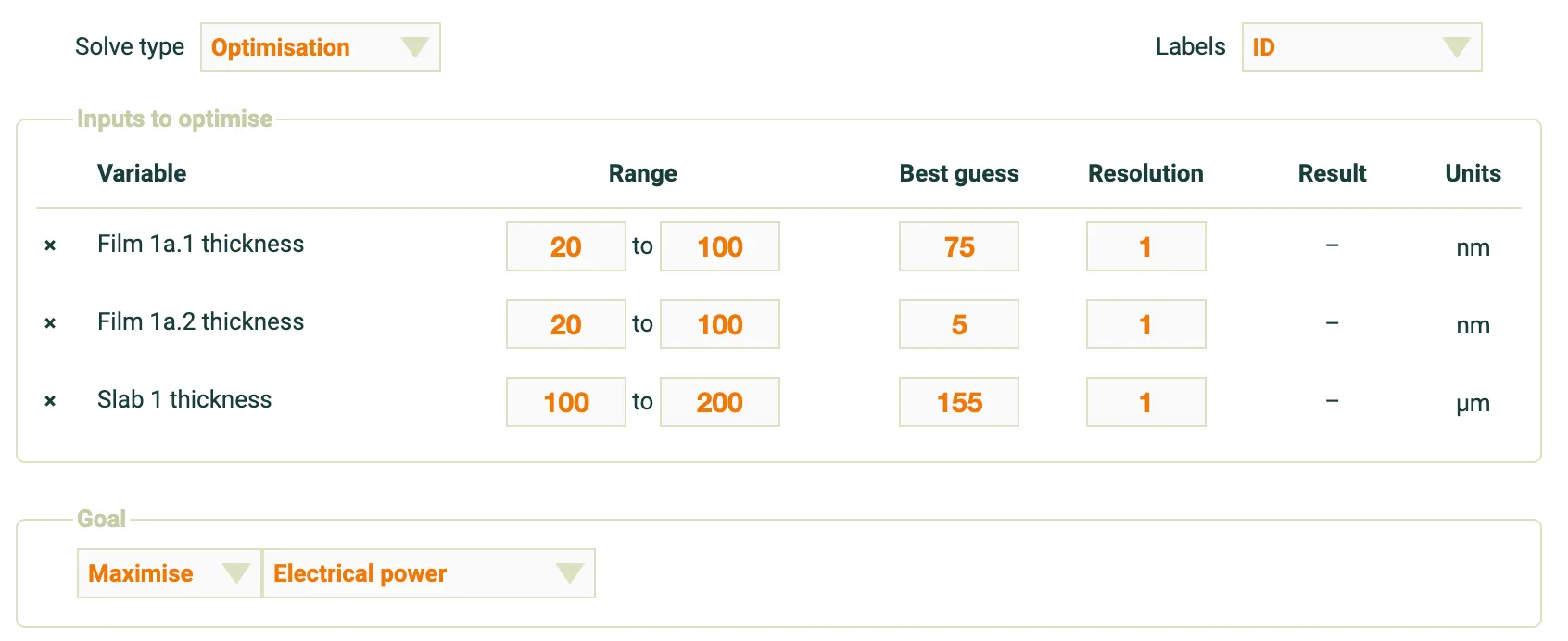
As solar cells become increasingly complex, optimizing cell design becomes more challenging. SunSolve 7 includes an automatic optimization system that enables engineers to find the highest performing cell designs automatically, reducing manual effort and accelerating development cycles.
To use the automatic optimiser, engineers start with a well-characterized model of their cell or module and select up to 3 variables to optimize. Many parameters in the SunSolve model can be included, such as the thickness of thin films or thick layers.
Once the variables are chosen, engineers can start the simulation and SunSolve will use a genetic algorithm to iterate through various options until it converges on the highest performing configuration.
Learn More About the Evolutionary Optimiser
For a comprehensive introduction to this powerful feature, read our detailed blog post: Introducing SunSolve’s Evolutionary Optimiser which covers the technical details of how the genetic algorithm works and provides real-world examples of optimization scenarios.
You can also watch our tutorial video: Using the SunSolve Power Input Optimiser for a step-by-step walkthrough of how to set up and run optimization routines in SunSolve Power.
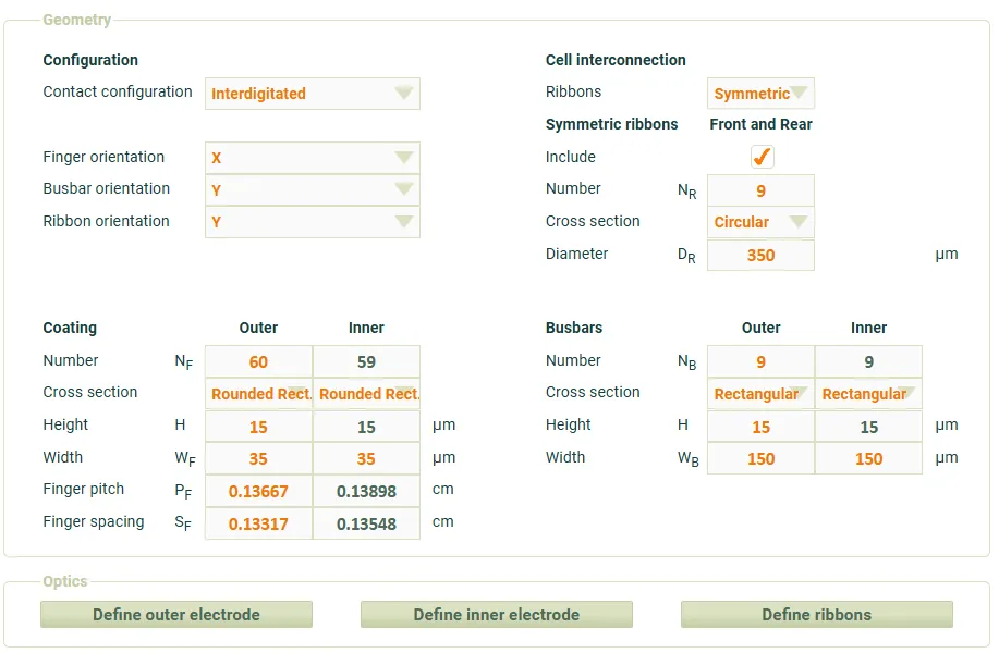
IBC metallisation pattern
A new contact configuration is being introduced to support all back contact cell designs, providing engineers with greater flexibility in modeling advanced cell architectures.
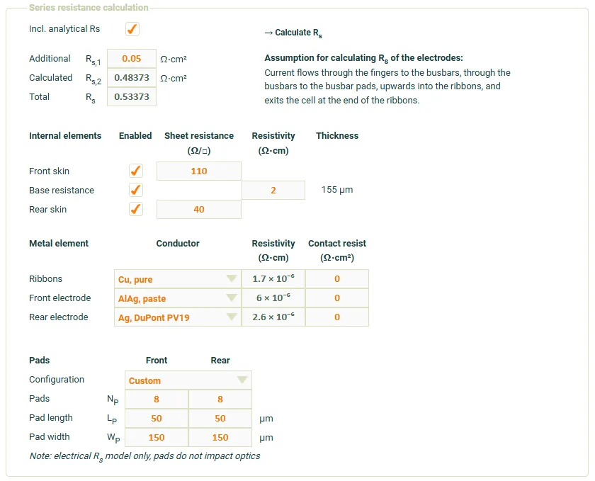
Improved control over the series resistance calculation
Version 7 now allows users full control over the contacting pads used in the electrical grid resistance calculation. This enhancement enables better definition of current flow changes when the number of solder joints or IV probes varies, leading to more accurate modeling of real-world conditions.
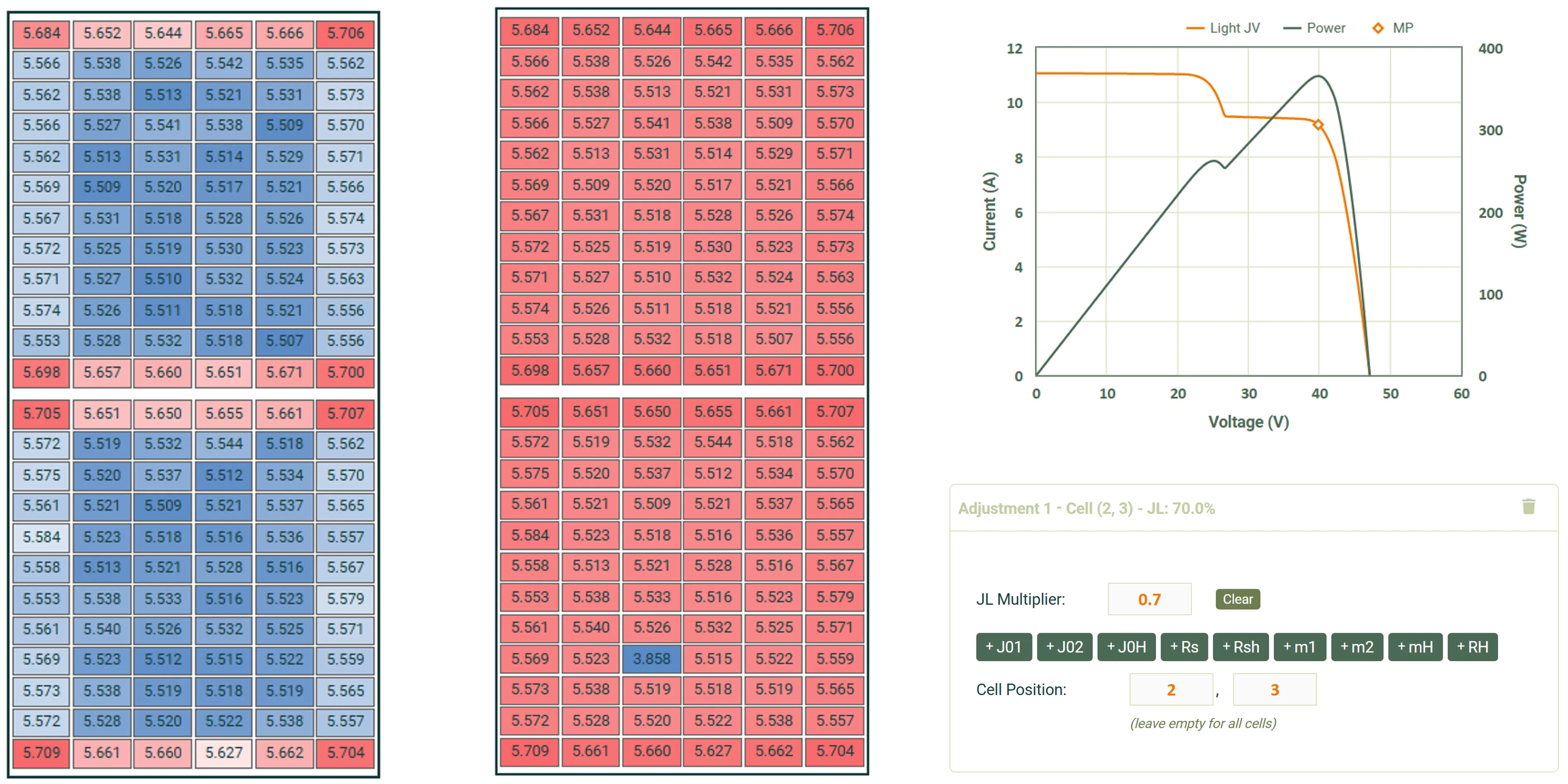
Cell-level variation in equivalent circuit inputs
Now available to advanced users on request, this powerful feature lets you fine-tune equivalent circuit inputs for a single cell or a defined group of cells. Variations are applied relatively, enabling both increases and decreases in input values.
Practical uses include:
- Hot-spot testing: simulate the effect of shading a single cell.
- Non-uniform irradiance modeling: test performance under uneven lighting conditions.
- Non-uniform soiling: model dirt, dust, or debris accumulation affecting certain cells.
- Localized degradation: replicate long-term wear, microcracks, or potential-induced degradation (PID) in specific areas.
- Manufacturing variability: explore the impact of cell-to-cell differences in electrical characteristics.
- Bypass diode triggering: study how cell-level mismatches activate protection circuits.
This capability opens new possibilities for advanced diagnostics, performance analysis, and next-generation PV design workflows.
Custom module electrical layout
Available to advanced users on request, this feature enables complete flexibility in defining module circuit wiring. You can configure any combination of connections between cells, bypass diodes, and terminals to match custom designs or experimental configurations.
It’s also possible to introduce resistive paths into the module to assess the impact of extended bus regions or other conductive variations.
Practical uses include:
- Designing and testing unconventional wiring topologies.
- Simulating the electrical effects of alternative bypass diode arrangements.
- Evaluating performance under partial connection failures.
- Investigating the impact of extended module bus regions.
- Modeling fault conditions and advanced R&D prototypes.
Future upgrades
All future upgrades to SunSolve will be applied to SunSolve Version 7, with SunSolve 6 receiving only critical bug fixes. New features coming soon include custom circuit layout definitions for modules and advanced temperature models for the electrical circuit.